2.1.1 – Basics – Basic Limit Switch IoT
Table of Content
Intro
Demo Video
Downloadables
Used Hardware
Wiring Diagram
Code Explanation
Helpful Links
Intro
In this tutorial, we will explore the development of a prototype that harnesses the power of Node-RED and MQTT to control the movement of a linear axis over a specified distance. From serving as a torch height controller in welding or plasma cutting operations to acting as a mount for a line scanner, the adaptability of this modified linear axis is quite useful.
If you don´t have the hardware but still want to try IoT ideas out you can use Wokwi and/or TinkerCAD to simulate the basic hardware with ESP32 and Arduino boards.
Demo Video
Downloadables
Used Hardware
-
- Linear Axis
- NEMA 23-02: Bipolar Stepper Motor
- 2H Microstep Driver DM420
- Power Supply MW RT-65D
- Limit Switch
- NodeMCU – ESP8266
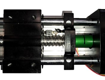
Linear Axis
A linear axis refers to the straight-line path along which an object can move or be moved. In the context of machinery, it’s a component that allows movement in a straight line, providing precise positioning in applications like welding or scanning.
NEMA 23-02: Bipolar Stepper Motor
A bipolar stepper motor is a type of motor with one winding per phase and no center tap. It can produce more torque than a unipolar stepper motor of the same size, but requires a more complex driver circuit that can reverse the current direction in each winding.
- 1.2 Nm
- 2.5A 3 V
- Shaft diameter: 6.35 mm
- Connection: 4 pin Female (JST male)
- Steps per revolution : 200
- 56 x 56 x 56 mm
- Angle: 1,8 °
- More detail at: Link
2H Microstep Driver DM420
A microstep driver is a device that controls stepper motors to achieve higher resolution or smoother motion at low speeds. It allows intermediate step locations by energizing the coils with intermediate current levels.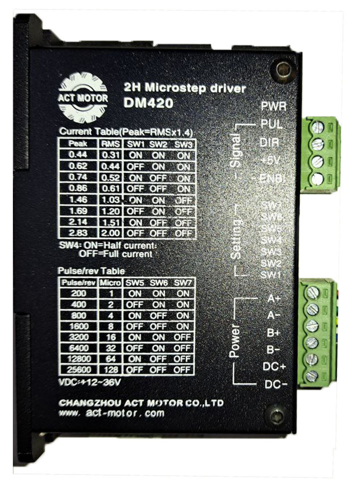
- DM420 is a two-phase hybrid stepper motor driver.
- Between 12VDC and 36V DC
- Output current: 0.44 – 2.83 A
- Input current: < 2.0 A
- More detail at: Link
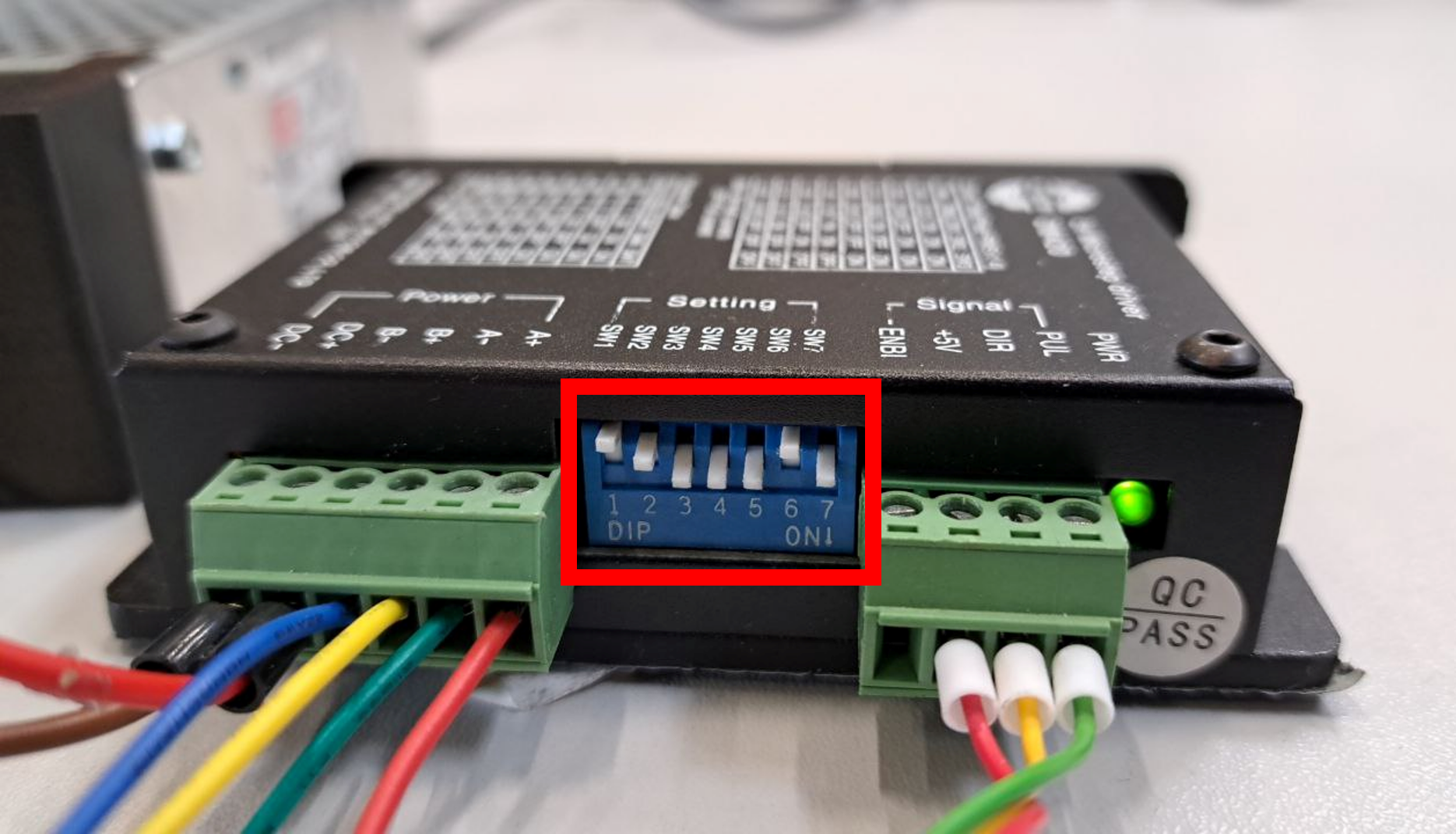
One of the key features of electrical microstep drivers is their ability to adjust the pulse and current sent to the motor. These settings are typically displayed on the driver itself in the form of a printed table, as well as in the datasheet. They are controlled by small DIP switches. The table indicates which switches should be turned on or off, depending on the desired settings.
Here’s a breakdown of our settings:
- Current Settings (SW1 to SW3): These switches control the current sent to the motor. In your case, “SW1” OFF, “SW2” OFF, “SW3” ON corresponds to a peak current of 0.86A and an RMS (Root Mean Square) current of 0.61A.
- Half/Full Current (SW4): This switch determines whether the driver outputs half or full current. In your case, “SW4” ON means that the driver is set to output half current. Therefore, the peak current will be 0.43A and the RMS current will be 0.305A.
- Microstep Settings (SW5 to SW7): These switches set the microstep resolution, which determines the number of pulses per revolution. In your case, “SW5” ON, “SW6” OFF, “SW7” ON corresponds to 800 pulses per revolution and a microstep size of 4.
Power Supply MW RT-65D
A power supply is a hardware component that supplies power to an electrical device. It receives power from an electrical outlet and converts the current from AC (alternating current) to DC (direct current), which is what the most IoT components require.
- Cased
- Screw connections
- Long Life 105°C electrolytic capacitors
- Output voltage: CH1: 5V / CH2: 24V / CH3: 12V
- Output current: CH1: 4A / CH2: 1.5A / CH3: 1A
- Power: 68 W
- 129 x 98 x 38 mm
- Protected against short circuit, overload, overvoltage
- More detail at: Link
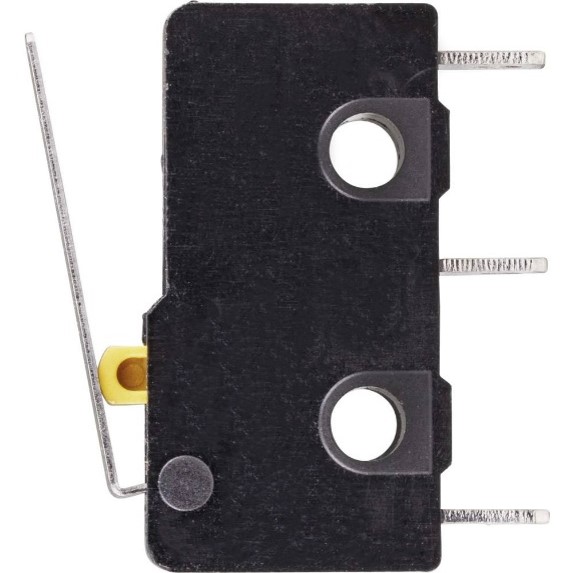
Limit Switch
A limit switch is an electro-mechanical device operated by the motion of a machine part or the presence of an object. It can be used for controlling machinery as part of a control system, as a safety interlock, or as a counter enumerating objects passing a point.
NodeMCU – ESP8266
The NodeMCU ESP8266 board is an open-source Lua based firmware and development board specially targeted for IoT based Applications. It includes firmware that runs on the ESP8266 Wi-Fi SoC from Espressif Systems, and hardware which is based on the ESP-12 module.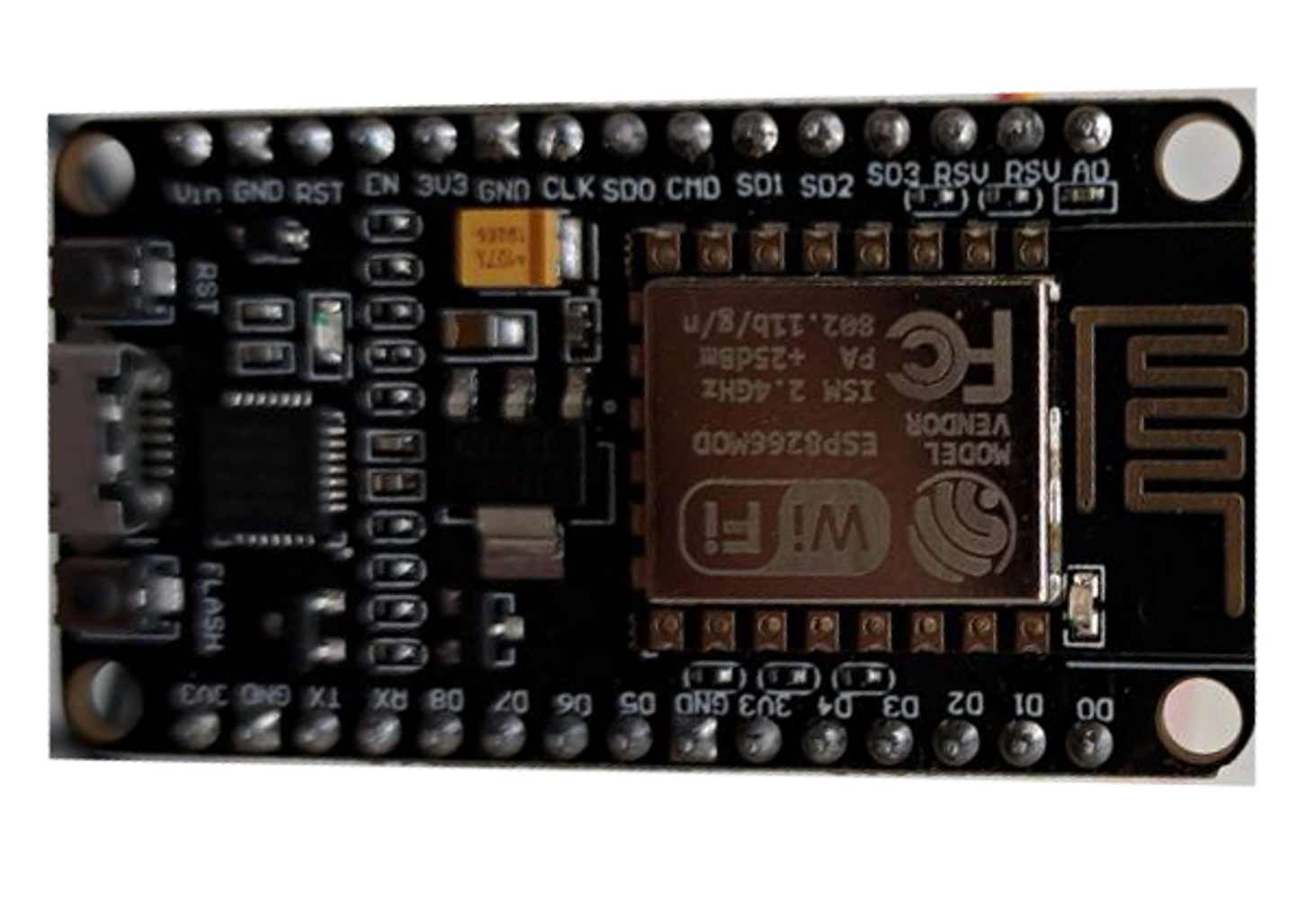
- Type: ESP-8266
- Clock Frequency: 80 – 160 MHz
- 49 x 26 x 13 mm
- Wi-Fi Chip
- Wireless Standard: 802.11 b/g/n
- Frequency: 2,4 GHz
- More detail at: Link
Wiring Diagram
In this section, we have provided the wiring details for the IoT-enabled linear axis setup. The gallery below presents an overview diagram, along with detailed images of the wiring for each complex component. (The images can be clicked on to see in detail.)


Code Explanation
The Declarations
To utilize the libraries, they must first be included in your code. With the EspMQTTClient library, an MQTT publisher client is created. This requires the WiFi name and password to enable the NodeMCU board to connect to the WiFi network and establish a connection with the MQTT server.
Once the client is set up, you can define the pins to be used (in this case, we used D5 (GPIO 14) for the limit switch and D6(GPIO 12) and D7(GPIO 13)). Additionally, you can set the maximum speed and acceleration of your stepper motor, as well as the steps and distance in millimeters.

The Setup Function
The setup function initializes the serial communication, enables MQTT client debugging, and sets the stepper motor’s maximum speed and acceleration. The switch pin is also set as an input with the pull-up resistor enabled. Finally, the home function is invoked to set the initial position of the stepper motor. The home function establishes a reference point for the linear axis by moving it to the limit switch and setting a new home position. This is done each time the linear axis starts to ensure correct calibration and operation within its defined range of motion.

The Loop Function
The loop() function, a fundamental part of Arduino programming, executes continuously until the device is reset or powered off. It repeatedly performs tasks such as reading sensors and controlling outputs. In this code, the loop function uses the MQTT client’s loop function to maintain a connection to the MQTT server and publishes a message to the “devices” topic with the device name every 500ms to ensure visibility on the MCU when connected.

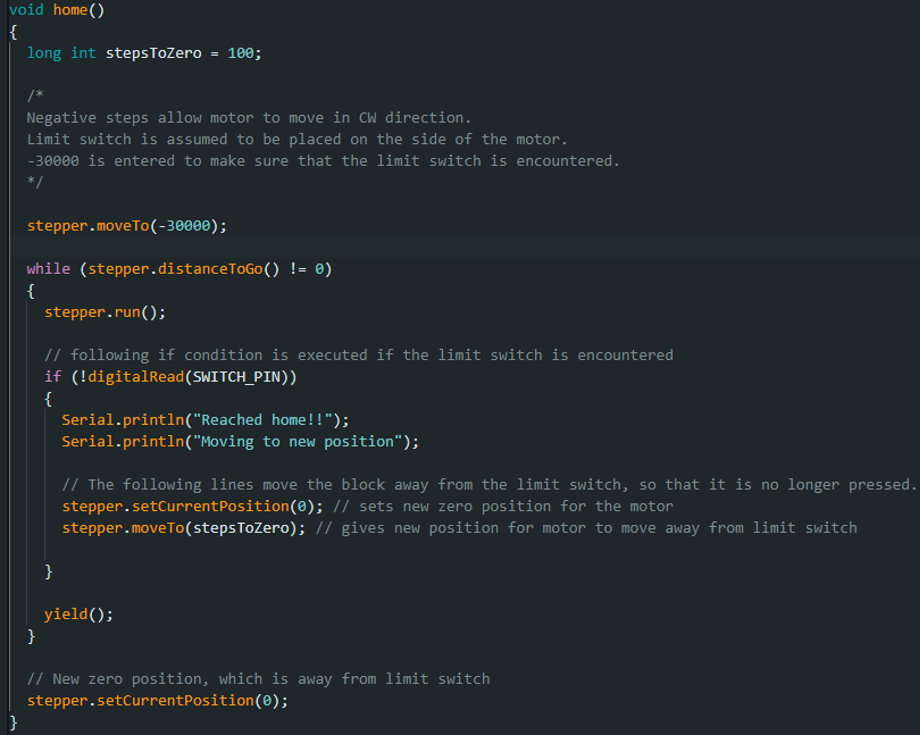
The Home Function
The home function moves the motor towards a limit switch until it is pressed, indicating that the motor has reached its initial position. Once the switch is pressed, the motor’s current position is set as the new zero position, and it is moved away from the switch by a specific number of steps.

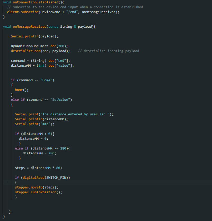
The onConnectionEstablished and onMessageReceived Functions
These two functions, onConnectionEstablished and onMessageReceived, work together to handle incoming commands from a Node-RED dashboard using JSON formatting. The former function subscribes to the device command input, while the latter function processes received messages. If the “Home” command is received, the home function is invoked, causing the motor to move towards the limit switch again. If the “SetValue” command is received with a specified value, the motor moves to the desired distance in millimeters. If the distance is less than zero, it is set to zero, and if it is greater than 280mm, it is capped at 280mm. This ensures that the limit switch never attempts to exceed its limits.

Node-Red – UI
As illustrated in the videos and gifs, the system is quite straightforward. It comprises three interactive components that enhance user interaction. The first component allows the user to adjust the target distance in millimeters. This adjustment can be made either by manually entering the value or by using the up and down buttons situated next to the text field. However, the system imposes pre-set limits on the linear axis, preventing the user from issuing commands beyond 280mm and below 0mm.
The second component is the command initiation button. This button must be pressed to transmit the value as a command. Without this action, the linear axis remains stationary.
The third component is the home button, which returns the linear axis to its initial position.
Finally, the ‘CMD’ section is located at the bottom of the group. This section displays the specific command sent to the MQTT server, as well as the information read by the pre-existing script. This feature enhances the system’s transparency, ensuring that the correct commands are sent and executed properly.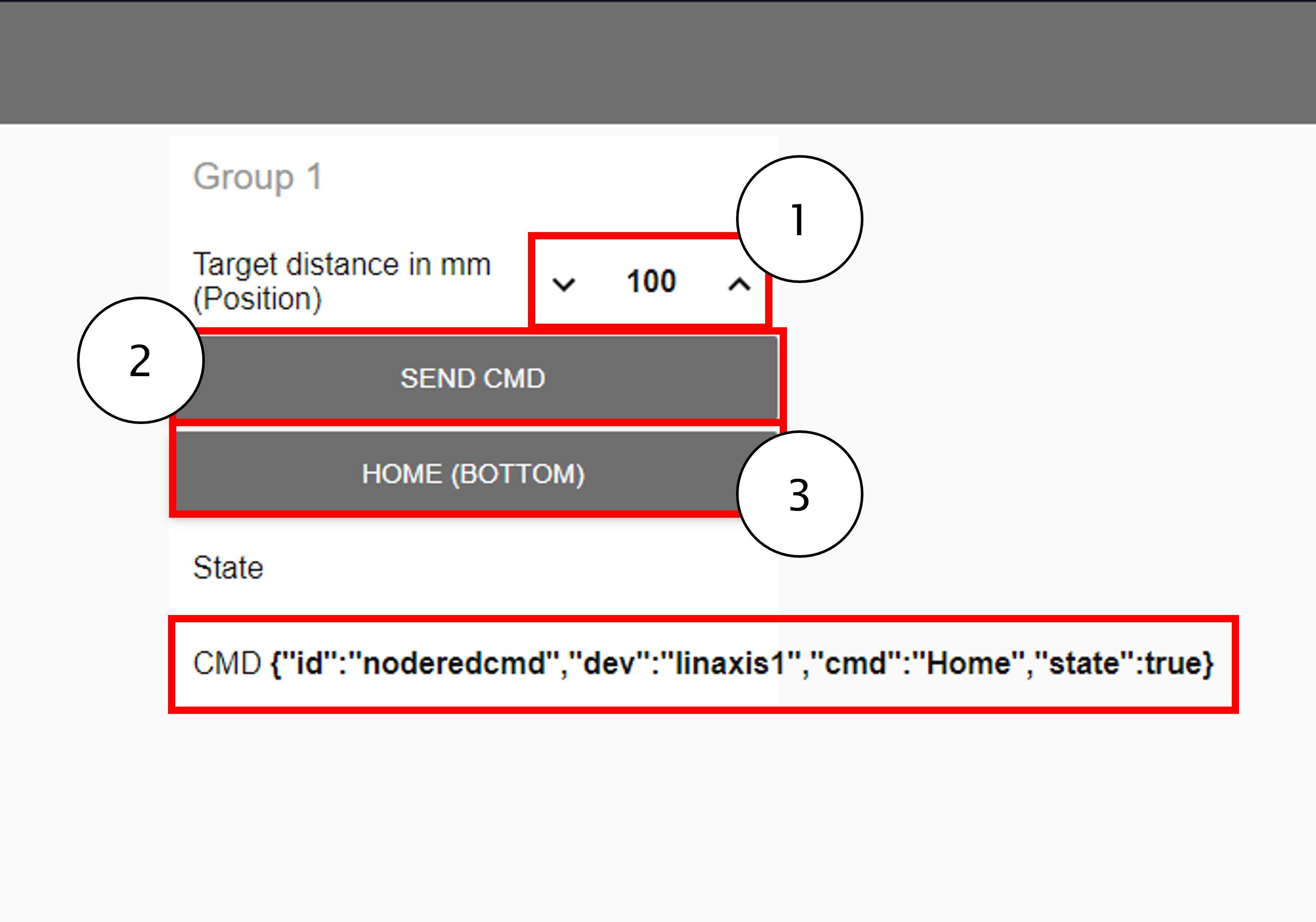
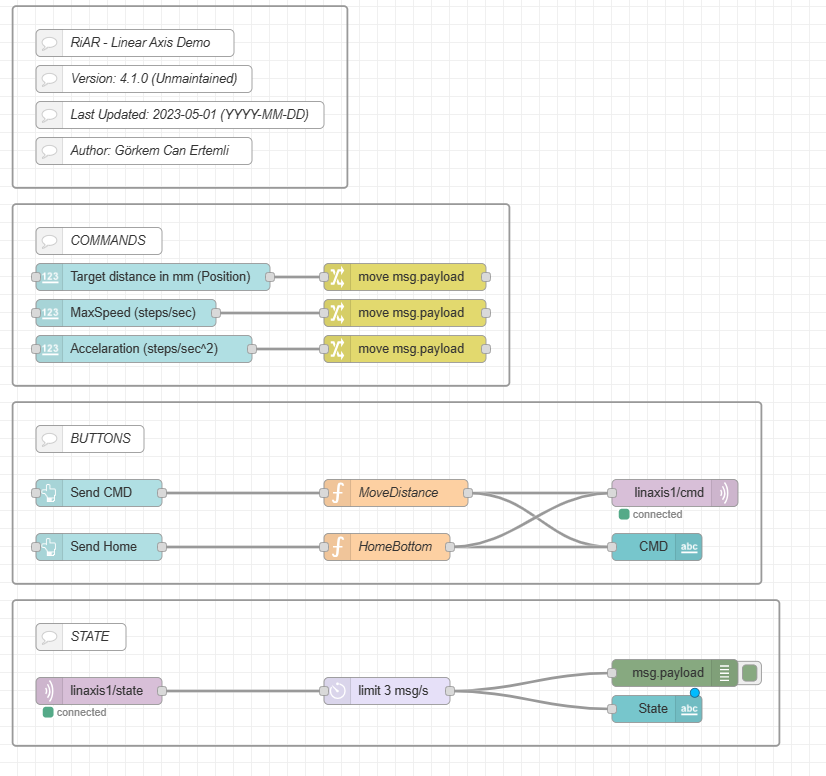
Node-Red – Flow
The Node-RED flow provided is divided into four specific sections. The initial section, known as the ‘info group’, encompasses details such as the name of the flow, its version, the date of the last update to the script, and the original author of the script. The second section consists of UI elements that will be used for CMD creation. Third part is responsible for the JSON Objects creation and sending the CMD to the device´s cmd topic. Last section is for checking the state of the device.
The process of command creation is uncomplicated and yields a JSON format that we explored in the basics lecture. It usually includes components such as “id”, “cmd”, “dev”, “sync”, and “state”. For a more in-depth understanding of JSON formatting, I recommend revisiting the basics section of the tutorials. In this instance, to mirror the code in the NodeMCU, we are utilizing “id”, “dev”, and “cmd”, “state” and “value”.
For the MoveDistance and HomeButton functions the JSON formatting from our lectures were used. The script used for these functions to generate the JSON format as follows:
//HomeButton
msg.payload = {};

msg.payload.id = "noderedcmd";
msg.payload.dev = "linaxis1";
msg.payload.cmd = "Home";

msg.payload.state = true;

return msg;
//MoveDistance
msg.payload = {};

msg.payload.id = "noderedcmd";
msg.payload.dev = "linaxis1";
msg.payload.cmd = "SetValue";

msg.payload.value = flow.get("distance");

return msg;
Please remember to modify the Broker Server of the MQTT in and out node when testing the script.